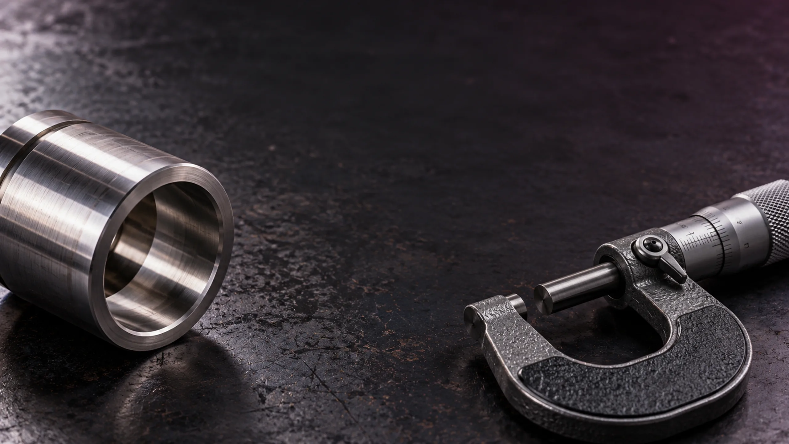
Precision-machined sleeve beside a micrometer on a dark workbench

Keep critical dimensions within

CNC turn-mill machining and precision grinding
Every number backed by measurement

Prototypes to medium runs · 24-hour drawing review (illustrative)

Read the tolerance band

Place the reading in its tolerance band

A reading close to nominal is not necessarily acceptable. This scale shows both limits and the measured position together.

Illustrative outside diameterØ20 ±0.005 mm
19.99019.99520.00020.00520.010

Current measurement

19.999 mm
Within tolerance

Acceptance range 19.995–20.005 mm
Assessed against the nominal size and drawing tolerance.

Measurement basis · Outside micrometer
A reading demonstration, not an actual inspection record.

±0.005 mm is an illustrative specification. Feasibility depends on size, material, geometric tolerances and machining conditions.

Set the datum
Then plan the machining sequence

Turning, milling, grinding and finishing follow the drawing. Confirm locating surfaces and measurement datums before choosing operations, fixtures and inspection points.

Machining experience
18 years (illustrative)
Small to medium runs
20–500 pieces
Quality system
ISO 9001 (illustrative)
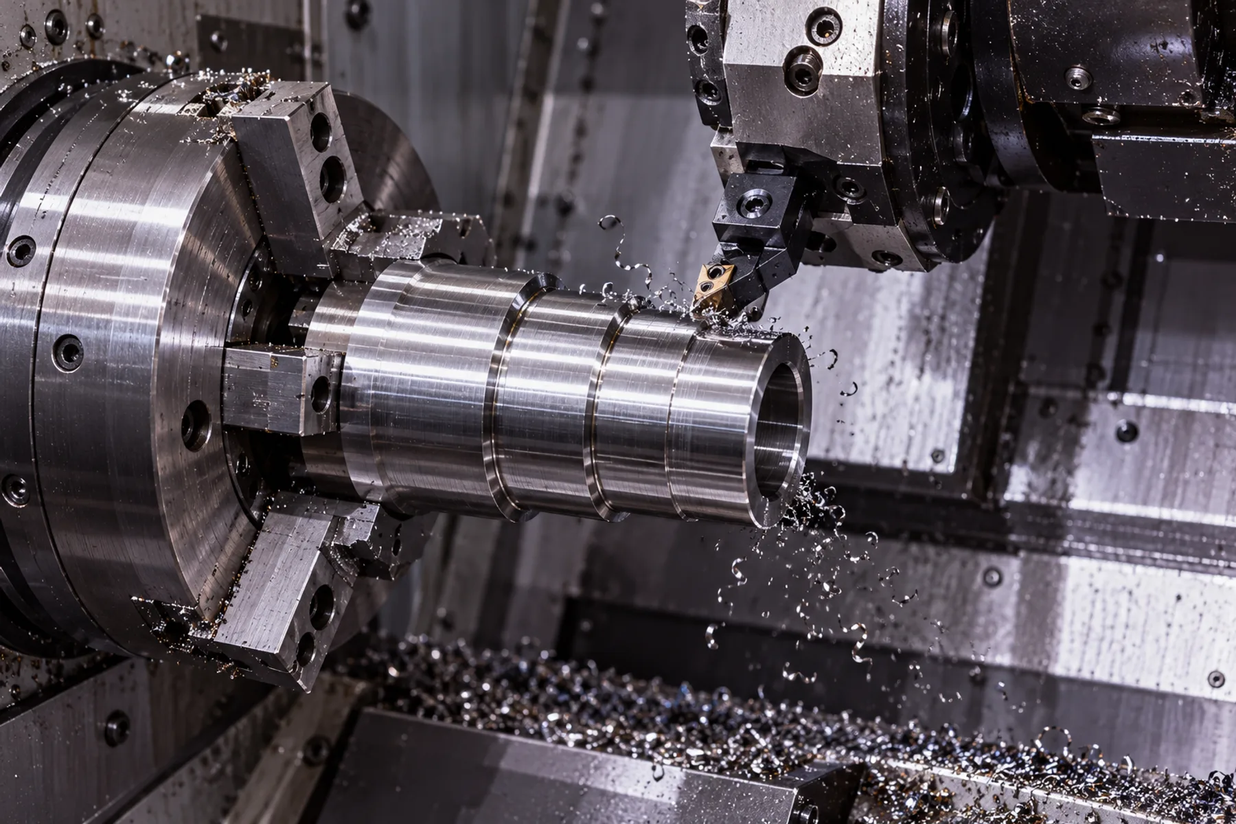
A CNC turn-mill tool machining a cylindrical steel component
Complete multiple operations from one setup datum

CNC turn-mill machining

Shafts, sleeves and multi-face components are assessed for single-setup machining first. Fewer relocations help control accumulated axial and face errors.

Maximum outside diameter Ø320 mmIllustrative tolerance ±0.005 mm
Maximum diameterØ320 mm
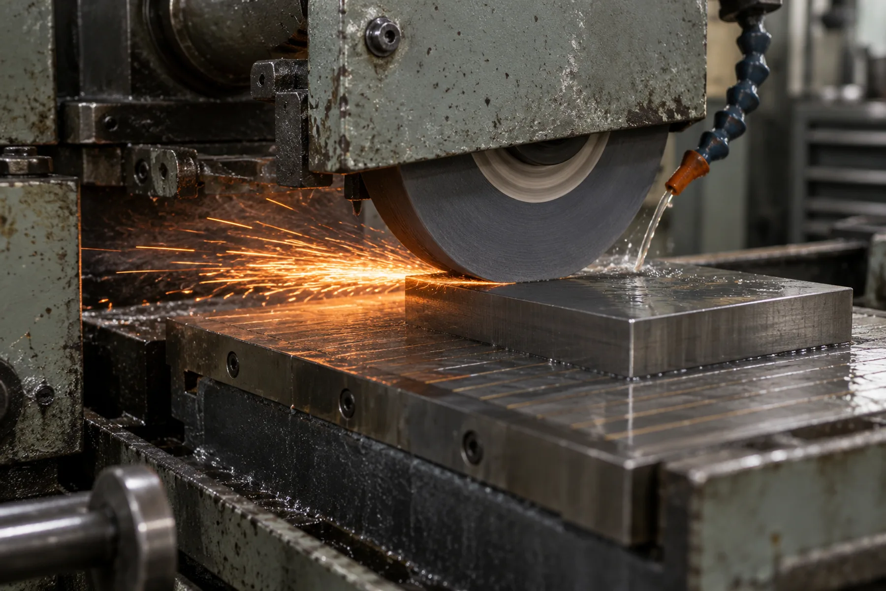
A precision grinding wheel meeting a steel workpiece on a magnetic chuck
Confirm grinding allowance and measurement conditions together

Precision grinding

Surface, internal, external and profile grinding begin with enough finishing allowance. Dimensions, roundness and surface roughness are checked separately; appearance does not replace measurement.

Illustrative roughness Ra 0.2 μmIllustrative roundness 0.003 mm
Surface roughnessRa 0.2 μm
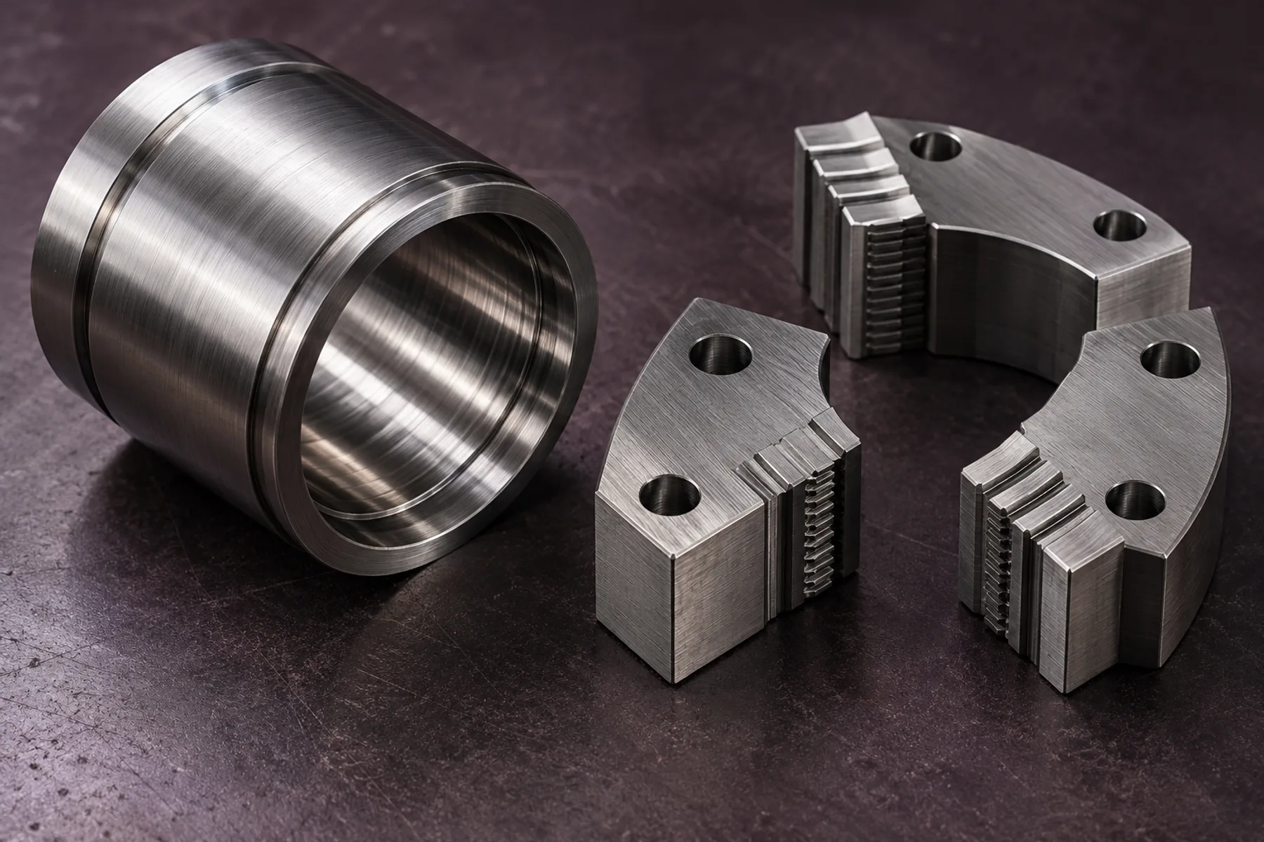
Close view of machining marks on a precision sleeve and custom soft jaws
A shared datum for locating, tool wear and batch records

Fixtures and production integration

Record locating methods, tool life and machining parameters from fixture development and first-article validation through production. Each batch links back to its operations, in-process checks and shipment records.

Production planning from 20 piecesControl basis: batch traceability
Minimum batch20+ pieces

Different materials
Different dimensional allowances

Strength, corrosion resistance, heat treatment and finish affect the process. Confirm material certificates with suppliers, then account for coating thickness and distortion in the dimensional assessment.

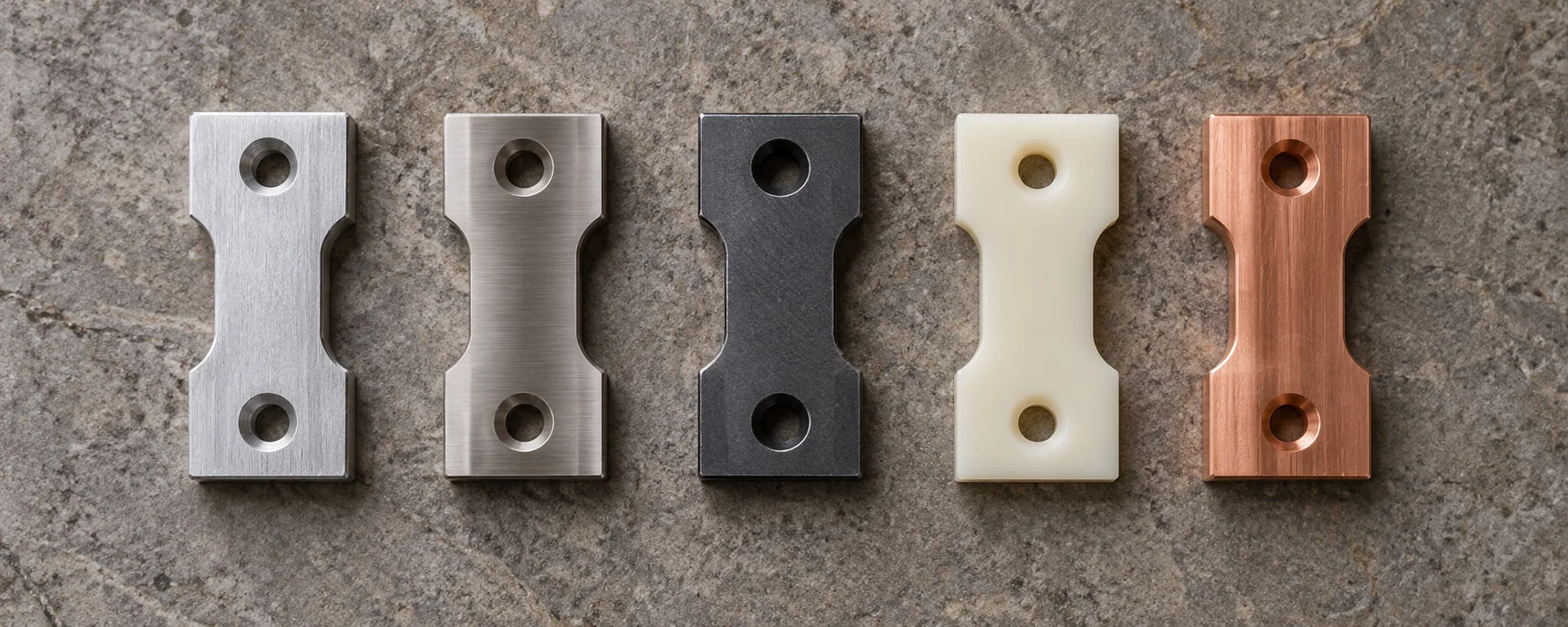
Aluminium, stainless steel, tool steel, engineering plastic and copper samples in a row
Five materials · One final dimensional datumRelative dimensional change · Removal ← 0 → Addition (illustrative)
01

Aluminium

6061 / 7075
Lightweight fixtures and structural parts

Anodising / Hard anodising
Confirm coating thickness and mating dimensions

02

Stainless steel

SUS303 / 304 / 316
Fluid-handling and medical equipment parts

Passivation / Electropolishing
Confirm corrosion resistance and surface acceptance criteria

03

Tool steel

SKD11 / SKH51
Moulds and wear-resistant parts

Heat treatment / Grinding
Confirm hardness and finishing stock after heat treatment

04

Engineering plastics

POM / PEEK / MC Nylon
Insulating and lightweight parts

Precision cutting
Confirm operating environment and measurement conditions

05

Copper alloys

C1100 / Brass
Conductive terminals and mechanical parts

Nickel / Tin plating
Confirm plating thickness and contact dimensions

Ranges are relative illustrations, not millimetres or a fixed ranking of materials. Actual dimensional changes are assessed against the approved drawing, grade and finishing conditions.

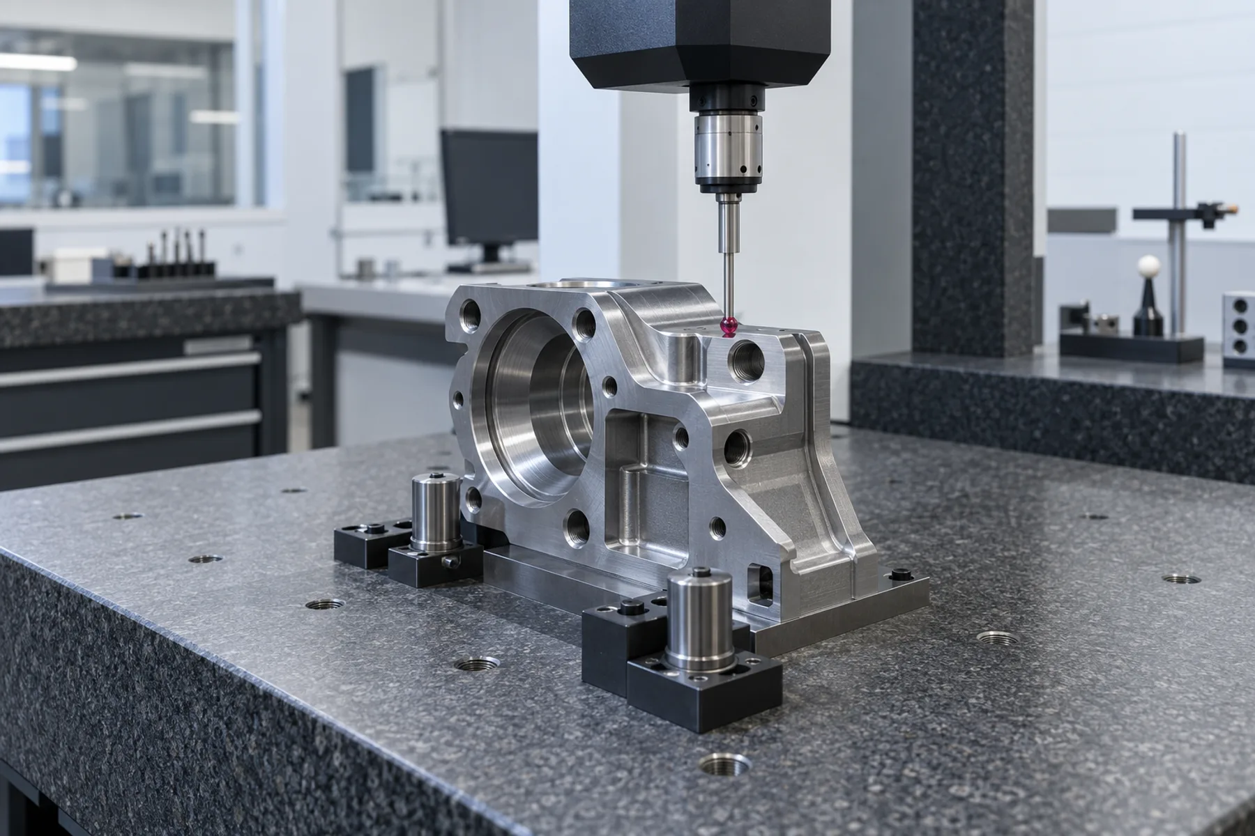
A coordinate measuring machine ruby probe touching a precision component

For every reading
Use the same acceptance basis

Measuring equipment is calibrated regularly. Align the drawing revision, datum, instrument and sampling method before comparing results between operations.

01 First-article dimensional check

Measure the first article before production, confirm drawing requirements and lock the machining conditions to keep the same error from reaching an entire batch.

02 In-process inspection

Set inspection frequency by risk, track dimensional drift and correct for tool wear and temperature effects.

03 Shipment report

Perform full dimensional or sampled inspection to the drawing after machining. Key dimensions, material certificates and finishing records accompany shipments as agreed.

Reports filed by batch · Processes and equipment images are illustrative
Match the fit
To its application

The application determines which dimensions matter. Review how and where a component is assembled and used before defining tolerances and measurement methods.

01

Automation

Slides, sleeves, locating parts and fixtures

02

Semiconductor support

Chamber accessories, sensor mounts and precision mechanisms

03

Medical equipment

Non-implantable equipment parts and stainless steel components

04

R&D prototypes

Design validation, short trial runs and fixture improvements

Five marks from drawing to delivery

  1. 01

    Drawing review

    Confirm material, tolerances, quantity and application, and establish dimensional datums.

  2. 02

    Process planning

    Arrange operations, tools, fixtures and inspection points.

  3. 03

    First-article trial

    Measure all dimensions, adjust parameters and confirm production conditions.

  4. 04

    Stable production

    Track dimensions through in-process checks and retain batch and exception records.

  5. 05

    Shipment and delivery

    Complete final inspection and packing, with the agreed inspection documents.

Fixture redesign · Illustrative project

From three setups
To one locating operation

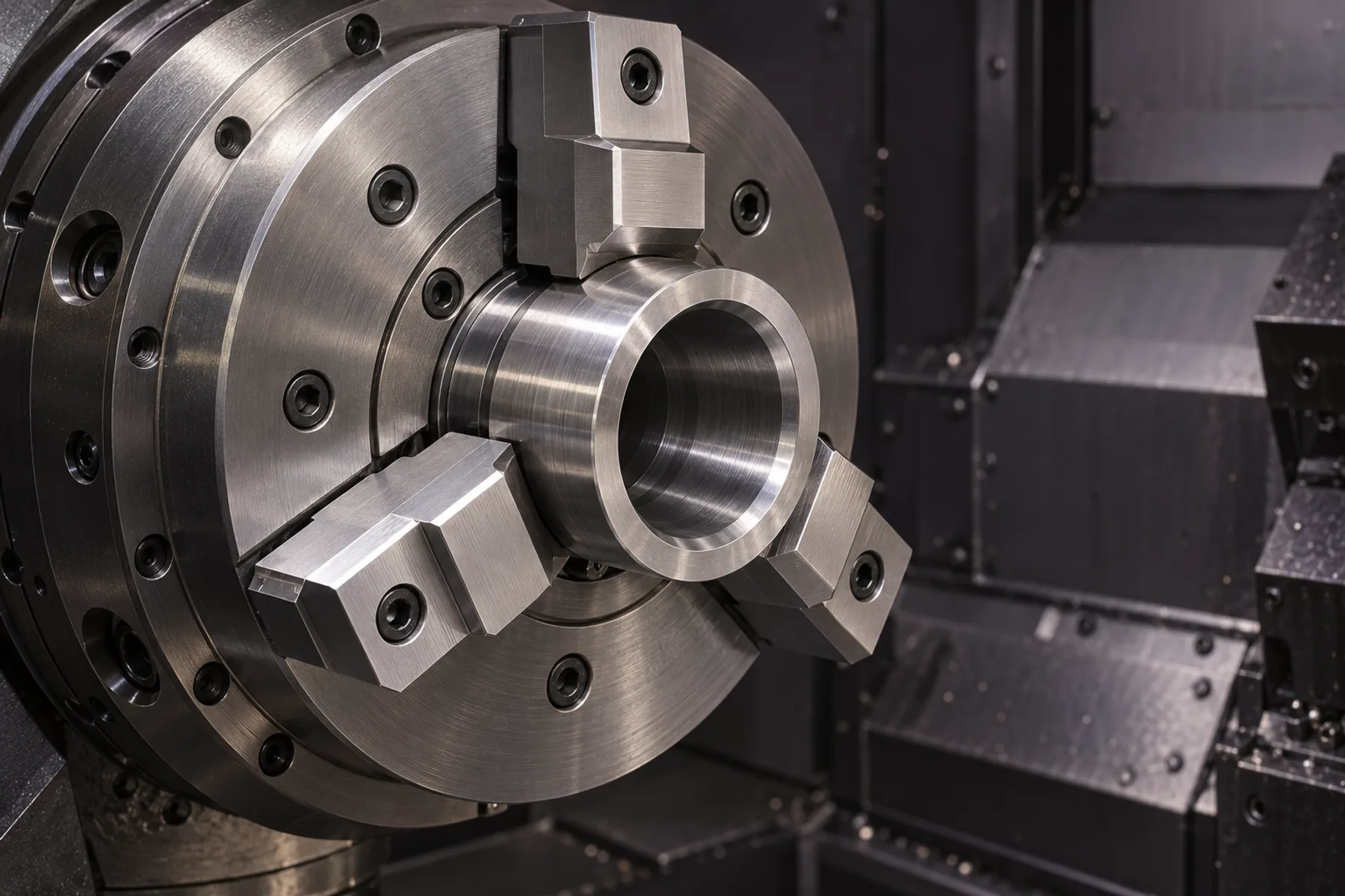
An automation sleeve originally required three setups, allowing concentricity to drift. Turn-mill machining and revised soft jaws reduce datum transfers, alongside tool-life management.

A steel sleeve clamped in three custom soft jaws inside a CNC turn-mill chuck
Dimensional distributions within one tolerance bandGrey: before / Mint: after
Lower limitNominal sizeUpper limit
97.8%First-batch yield (illustrative)
−32%Time per part (illustrative)

The curves illustrate a narrower distribution; they are not measured data or a statistical analysis. Yield and time figures are illustrative values from the original concept, not actual client results.

Before a quote
Check each measurement condition

Complete information makes process and delivery assessment easier. Tick the items you have prepared, then send the details by email.

0 / 4

Items prepared

Ticks are only for this page. No information is uploaded or stored.

Suggested files PDF / STEP / IGES / DWGIllustrative file specification · Up to 50 MB per file

Bring the drawing
Define a feasible tolerance

Include the drawing revision, material, estimated quantity and desired delivery date. A preliminary feasibility reply within one working day is followed by machining and inspection planning.

Send quote details
[email protected]04-2000-6888 (illustrative)

Juheng Precision is a fictional brand. The email, phone number, response time and service terms are design examples; no live quotation service is provided.

中文